Chapter 4 - Set Points & Alarms
User Set Points and the Alarm Log
xView can define set points as operating conditions. When a set point reaches the value configured for it, it can trigger an action — which makes set points well suited to raising alerts, and to automatic or semi-automatic control.
The system can also be configured to alert the user when defined events occur, though this requires a computer with multimedia hardware.
Only a Supervisor may enter this function. Use Controls > User Set Points.
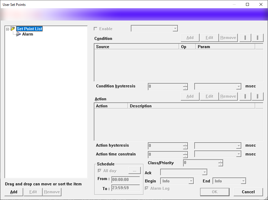
Figure 89 — User Set Points dialog
The dialog contains the following.
-
Set Point List — every set point defined in the system, with Add / Edit / Remove buttons for managing the entries.
-
Enable — whether this set point runs or is temporarily stopped. It is normally ticked, meaning the set point is active.
-
Condition — the logical condition. There may be one condition or several; each carries a conjunction (Or, And) along with the Source, Op and Param columns, so that the condition matches exactly what you intend before the action is carried out. When the condition is true, the action runs. For how the conjunctions behave, see the truth tables. The condition is evaluated from top to bottom. The Add / Edit / Remove / ↓ / ↑ buttons manage the order.
-
Action — what to do when the whole condition evaluates true. It has Action and Description columns, with Add / Edit / Remove / ↓ / ↑ buttons.
The available actions are:
-
(None) — do nothing.
-
Play — sound an alert through the multimedia system. Press
 to choose the sound file, and
 to test it. Loop repeats the sound continuously
for as long as the event lasts.
to test it. Loop repeats the sound continuously
for as long as the event lasts.
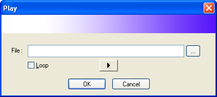
Figure 90 — Play dialog: the sound file, the ☑ Loop option, the ▶ test button and OK/Cancel
- Activate — used with PLCs, I/O modules or system flags to switch load for energy saving. The output follows the real state of the condition immediately.
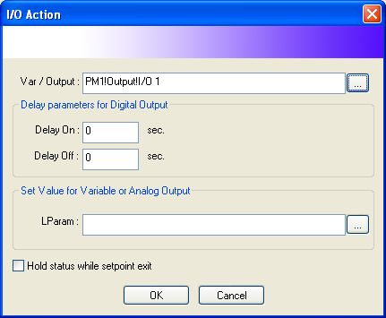
Figure 91 — I/O Action dialog: Var/Output (for example PM1!Output!I/O 1);
Delay parameters for Digital Output (Delay On/Off, in seconds); Set Value
for Variable or Analog Output (LParam); ☑ Hold status while setpoint exit
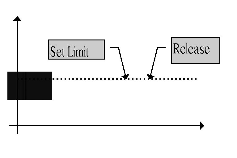
Figure 92 — How the Activate action behaves (diagram)
- Set — also used with PLCs, I/O modules or system flags to switch load for energy saving. It sets the limit only when the condition is true, and holds that state until an UnSet condition arrives from another set point. When using Set you must also fill in "Set Value for Variable or Analog Output".
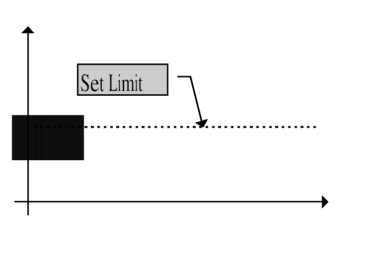
Figure 93 — How the Set action behaves (diagram)
- UnSet — likewise used with PLCs, I/O modules or system flags. It releases the limit when the condition is true; the load must have been set beforehand for there to be anything to release.
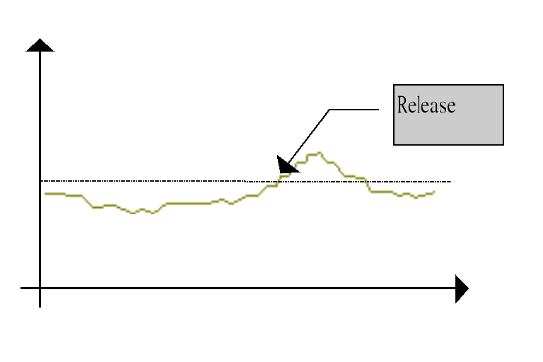
Figure 94 — How the UnSet action behaves (diagram)
- Send Pager/SMS — sends a message out over a pager, such as a PacLink
- It requires Pager.exe, an add-on program that sends both numeric and Thai/English text messages over a pager when an event begins (Message Begin) and when it ends. Sending SMS requires a GSM modem and a separate SMS add-on program.
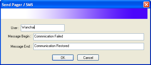
Figure 95 — Send Pager/SMS dialog: User, Message Begin, Message End
- Message — sends a message over the network to another computer connected by TCP/IP. It requires Messenger.exe, an add-on program that sends messages over the network when events occur.

Figure 96 — Message dialog: Message Begin/End; Popup Window (☑ Enable, ☑ Auto Close in 10 secs.); Network Send (☐ Enable, Network User); Say (☑ Enable, Voice: Microsoft Mike)
You can set the message shown when the event begins and when it ends.
Popup Window determines whether the message is shown on screen, and can be set to dismiss it after a given time (Auto Close in ... secs.).
Network Send sends the message over the network to the user named in Network User.
Say has the program synthesise speech from the message text (for example with the voice Microsoft Mike).
Within the message text you can wrap a reference in tags — <%= at the start and
%> at the end — so that the program looks the real value up in the data table
and substitutes it.
- Open — opens a file, or runs another program, when the event occurs; for example an MMI page related to that event (an interrupt screen).
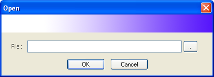
Figure 97 — Open dialog: File (path, with a ... button)
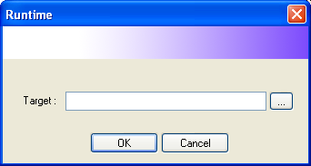
- Runtime — has the program time the event and accumulate the elapsed time into the variable named in Target. That variable should be a SaveVars variable so that it accumulates continuously. (The result is displayed in the MMI — see the MMI manual.)
Figure 98 — Runtime dialog: Target (path, with a ... button)
- Script (advanced use only) — has the system run the VBScript or JScript you nominate when the condition is met. It can be set to run when the event begins (OnBegin), while it continues (OnRun) and when it ends (OnEnd). (For more, see Microsoft's VBScript for Applications documentation.)
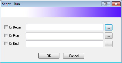
Figure 99 — Script-Run dialog: the script files for OnBegin, OnRun and OnEnd
-
Schedule — the time span over which this set point takes effect. To have it apply at all times, tick ☑ All day.
-
Alarm Log — whether the system records the result in the alarm log.
-
Begin and End — the priority, or category, of this set point as shown in the MMI system. Different categories give different colours, or different behaviour according to the priority you want. They can be set independently for Set Limit and for Release. (They are normally set to Warning and Info respectively.)
Table 6 — Set point categories
| Level | Set point category |
|---|---|
| 1 | Info, or Information |
| 2 | Warning |
| 3 | Error |
| 4 | Fatal, or Fatal Error |
| 5 | System, or System Message |
| 6 | Test, or Test Message |