Communication Channel Types
| Interface type | Description | Remarks |
|---|---|---|
| Standard COM Port | Serial COM1 to COM12 (RS232/RS422/RS485) | Cannot be removed |
| Hardware I/O | For ISA or PCI bus hardware installed directly in the machine | Includes ISA on PC104; cannot be removed |
| ETC Network | For reaching devices through an ETC2000 or ETC2002 over a TCP/IP network | |
| Direct Modem | For reaching devices over a modem |
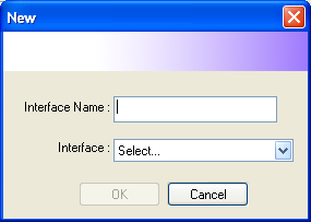 

Figure 37 — Adding a communication channel
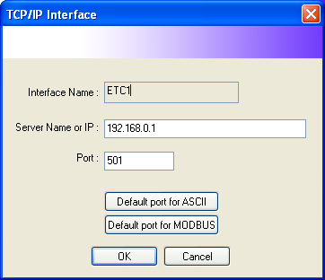
Figure 38 — Example of the TCP/IP interface settings
The TCP/IP interface fields are:
- Interface Name — the name given to this interface
- Server Name or IP — the IP address or host name of the device
- Port — the port number used for the connection
- Default port for ASCII and Default port for MODBUS — buttons that fill in the standard port automatically
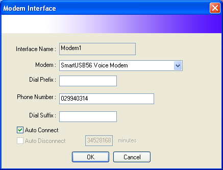
Figure 39 — Example of the modem interface settings
The modem interface fields are:
- Interface Name — the name given to this interface
- Modem — the modem installed in the machine that will be used
- Dial Prefix / Dial Suffix — strings dialled before and after the phone number, if any
- Phone Number — the phone number of the remote device
- Auto Connect — when ticked, the system connects automatically
13. Device Setup
Sets how many meters are connected to the system, and which models, over the communication channels covered above. The details are shown below.
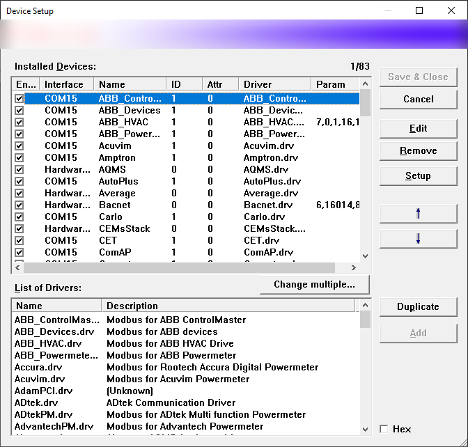
Figure 40 — Defining the devices in the system
Details:
-
Installed Devices — the list of devices installed in the system, showing the Enable (E), Interface, Name, ID, Driver and Param columns. The buttons are Edit, Remove, Setup (device properties) and the ↑ / ↓ arrows for reordering.
-
List of Drivers — the drivers available in the system (the part that handles communication with external devices). Duplicate copies the selected device; Add adds a new one.
The number of devices that can be defined or added here depends on your software licence. With a 32-device licence, for example, no more than 32 installed devices can be added and enabled. Similarly, the number of tags or I/O per device depends on the driver in use — some drivers offer only 8 tags, others as many as 512 — and this too depends on the licence.
Adding a device
Select the driver you want from the list of devices and press Add. The following dialog appears.
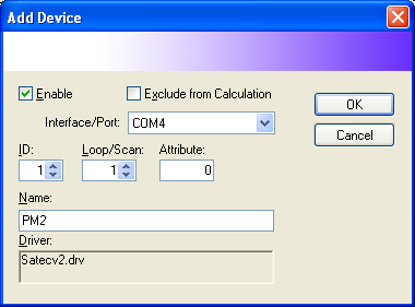
Figure 41 — Settings for the device being added
What the fields mean:
-
Enable — whether this device runs or is stopped. Normally it should stay ticked at all times. The exception is when a device has been removed temporarily for maintenance, when you may suspend it by clearing the tick so that it does not affect the polling cycle.
-
Exclude from Calculation — whether this device takes part in the system's totals and averages. Normally it should be left unticked.
-
Interface/Port — the communication channel the device is connected to, which must match a channel enabled under File → Communication Setup.
-
ID — the device's communication address. It normally starts from 1 and must match the address configured in the device itself. For a Digital Powermeter it must match the Adr (address) setting, and no two devices may share it.
-
Loop/Scan — the polling interval for the device. A larger number here makes transfers slower, which suits less important devices. The default is 1.
-
Attribute — an additional device property, as defined by the driver. The default is 0.
-
Name — the name given to the device. Make it meaningful and as short as possible, and do not use a comma (,). A Digital Powermeter on transformer 1, for example, might be called TR1 or PM1. This name should not be changed afterwards, because doing so breaks the references to it elsewhere in the system. When done, press
 .
.
Editing an installed device
-
Select the device you want to change from Installed Devices and press
 .
. -
A dialog appears with the device's settings, identical to the one used when the device was first installed, and the same settings can be changed.
-
The Duplicate button makes it easy to copy a device.
Notes
-
Take care not to change a device's name once windows referring to that device have been created, as this causes errors in both data recording and display.
-
Some device types — PLCs, chillers, remote displays — are forced to Exclude from Calculation.
-
Some device types, such as remote displays, cannot be given an ID.
Removing an installed device
To remove an installed device from the system, select it under Installed
Devices and press  .
.
Setting the device properties
Every device type has different properties. For a Digital Powermeter, pressing
 brings up the dialog shown below.
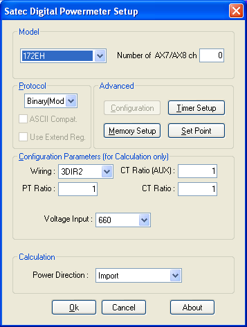
Figure 42 — Setting the device properties (SATEC Digital Powermeter Setup)
The important parts of this dialog are:
- Model — the meter model, and the number of AX7/AX8 channels
- Protocol — the protocol used (Binary/Modbus), with the ASCII Compat. and Use Extend Reg. options
- Advanced — the Timer Setup, Memory Setup and Set Point buttons
- Configuration Parameters (used for calculation only) — Wiring, CT Ratio (AUX), PT Ratio, CT Ratio, Voltage Input
- Power Direction (Import/Export)
Note
See the Appendix for each device type.
Cautions
-
Once the system is installed and recording, reordering the devices affects the display of historical graphs.
-
A device name must not contain characters that Windows disallows in file names, such as "/" or "\", nor a comma (,).
14. Group Setup
Defines groups for those electrical values that can meaningfully be totalled together.
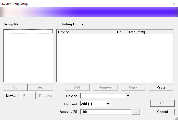
Figure 43 — Device Group Setup
As the illustration shows, calculation groups can be defined freely. Use the New... / Edit... / Remove buttons to manage the group names on the left; the panel on the right lists the devices in that group that will be totalled. Choose a device from the Device dropdown and set the Amount (%) — the proportion that contributes to the total, normally 100%.
Defining a group creates a virtual powermeter in the system. You can see it under View → Data Table, and everywhere a Source can be chosen the name (in this example "Incoming") appears alongside the real devices.
15. Computation Formula
Where you need a value that the program does not calculate automatically, you can build your own arithmetic formula through this menu. In the example, the average voltage is calculated and assigned to
SaveVars!Var 1, which can then be picked from Source anywhere in the program.
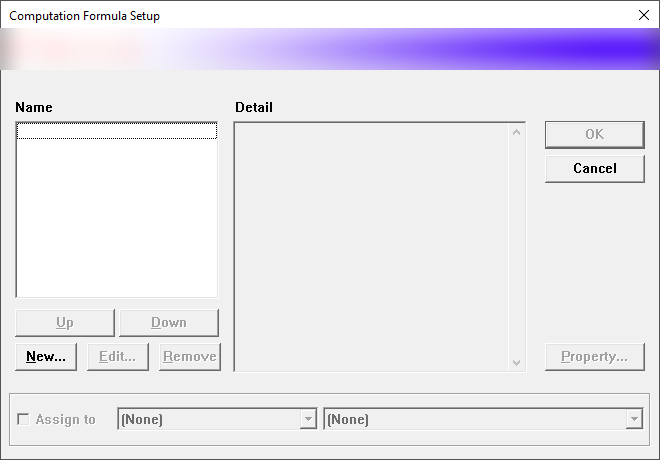
Figure 44 — Computation Formula Setup
16. Parameters Setup
Used to rename parameters such as Var, SaveVars or Flag, and the various I/O.
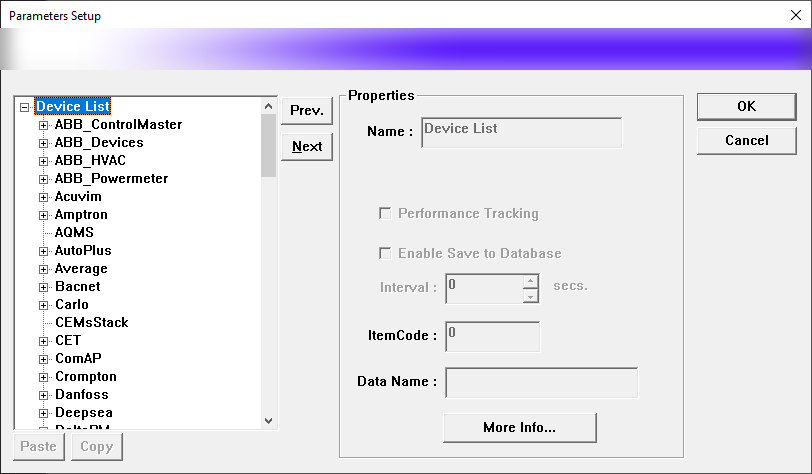
Figure 45 — Parameters Setup
The left-hand side shows the device list structure — for example PM1 > Basic, General, CalcValue, Input (including I/O), Output and ExtendedStatus. The Properties panel on the right holds Name, Performance Tracking (tracks the device's performance), Enable Save to Database with its Interval (the recording interval in seconds), and ItemCode for the database record.
Enable Save to Database writes the data to the Enterprise database at the given Interval (default 300 seconds), under the ItemCode used to reference it in the database.
-
Once the system is installed and recording, renaming a parameter affects the MMI system and control.
-
A name must not contain characters that Windows disallows in file names, such as "/" or "\", nor a comma (,).
17. Log On/Off
Identifies you so that you can use the commands. The program shows a password dialog (the Enter Password box). Enter the correct password and you can use the system at the level configured for it. Enter the wrong password and the program locks itself, preventing the use of most commands.
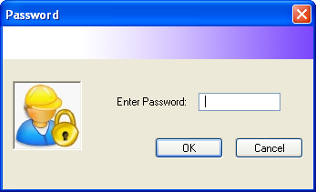
Figure 46 — Password dialog for identifying yourself before working
Note
See How passwords work for details.
18. Exit
Shuts xView down. A confirmation dialog appears, as shown.
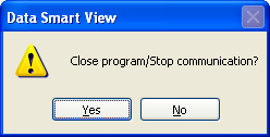
Figure 47 — Shutdown confirmation dialog (Close program / Stop communication?)
Choosing  shuts the program down — which means no data is
transferred for the whole time it is closed.
shuts the program down — which means no data is
transferred for the whole time it is closed.
Note
No data at all is recorded while the program is closed, so the data for that period cannot be reviewed afterwards.